Frequency Response Analysis
If you cannot measure it, you cannot improve it.
Lord Kelvin, Inventor (19th century)
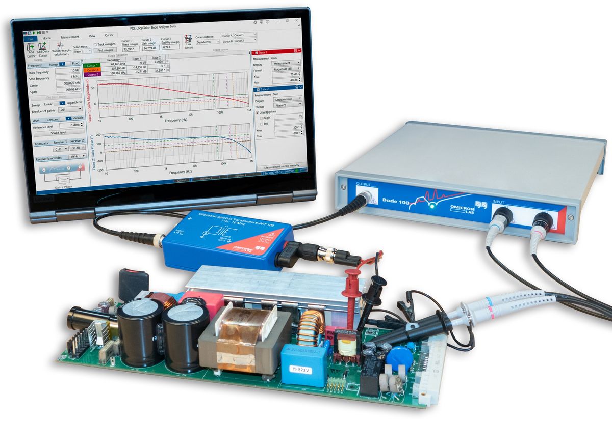
The Bode Analyzers, Bode 100 & Bode 500, are the professional solution to perform accurate and fast frequency sweep measurements from 1 Hz to 50 MHz or mHz to 450 MHz, essential for power supply design and stable loop operation.
The dedicated hardware offers fast sweep performance together with unsurpassed noise rejection allowing high-dynamic range measurements not only on passive components and linear regulators but also on switching converters.
Together with the Bode Analyzer Suite the Bode 100 & Bode 500 are the perfect choice to equip your design lab.
It enables you to analyze systems, control loops, electronic components and much more at a great price-performance ratio. The Bode Analyzers do not only offer frequency response analysis (FRA) but also vector network analysis (VNA) & impedance analyzer capabilities. Equip yourself and become a happy Bode-User!
Power Electronics Design & Analysis
Measuring a transfer function via frequency response analysis is a powerful method for the design of electronic systems such as compensators for switching converters or voltage regulators. The Bode Analyzer hardware and software are optimized for loop and impedance measurements, stability analysis and much more. Have a look at the following main applications in power electronics to find out how the Bode 100 & Bode 500 can support you in your design process:
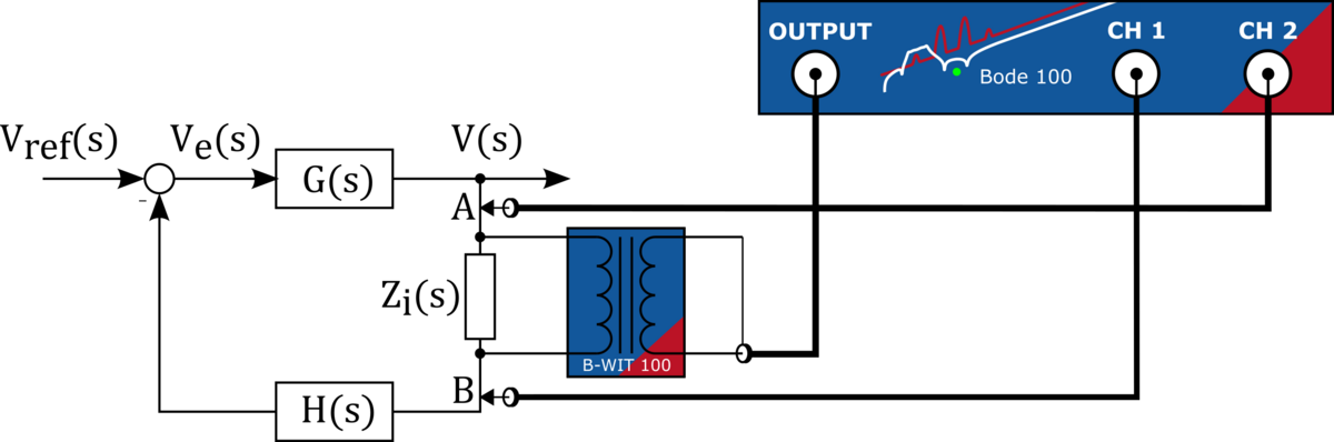
Loop Gain (Phase Margin & Gain Margin)
One of the most important steps when characterising or designing the control loop for a power converter. The Bode 100 offers high side-band rejection and a high dynamic range at an unbeatable measurement speed. Perform loop-response measurements within seconds to fully characterise your control loop at various operating points and conditions. Check out how quick and simple stability measurements can be and have a look at our Application Note.
Companion Power Supply Design Software for Bode 100 & Bode 500
Working in perfect harmony with Biricha's WDS automated power supply design software, the Bode Analyzers help to greatly reduce the development time and cost of your power supplies. Use WDS to design stable analog and digitally controlled power supplies in minutes!
The WDS power supply design software from Biricha simplifies power supply design and includes automatic pole-zero placement for optimum compensation. Besides the included topologies such as Buck, Boost, Buck-Boost, Flyback, SEPIC, Full bridge, Half bridge and forward converters, WDS now features the possibility to import a measured plant transfer function from the Bode Analyzers to design a stable compensator. Check out this webinar from Dr. Ali Shirsavar to learn more about this simple and innovative solution.
Output Impedance (Non-Invasive Stability Measurement)
The output impedance plot contains information about the stability of the feedback loop as well as information about the decoupling network. Use the NISM (Non-Invasive Stability Measurement) method to derive the phase margin from a single output impedance measurement. Check out this Application Note to learn how to perform this simple and fast measurement. Check out the Picotest accessories for simplified power integrity measurements.

Input Impedance & Filter Stability
The negative input resistance of a DC/DC converter can lead to oscillations when using an undamped input filter. The Bode 100 provides the possibility to check the input impedance of the converter as well as the impedance spectrum of the filter that could lead to instability problems at resonance. Check out the Application Note on input filter stability to find out more.

Component Impedance Plot
The impedance plot of electronic components provide a deep insight into the AC properties such as capacitor ESR, transformer leakage, AC resistance of windings, self-resonance frequency of inductors and transformers, inductance of shunt-resistors, winding capacitance of transformers etc. Use the Bode 100 (and Bode 500) to perform fast and accurate impedance measurements from 1 Hz to 50 MHz (or mHz to 450 MHz). Check out our webinar to learn more about the power of the Bode Analyzers when used as an impedance analyzer.
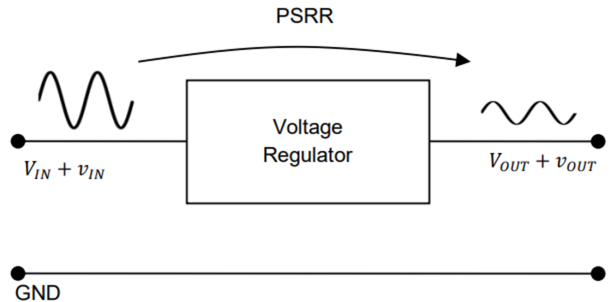
Power Supply Rejection Ratio (PSRR)
The power supply rejection ratio, also known as power supply ripple rejection, provides information on how well line-disturbances are rejected at the output. This information is especially useful for low-noise supplies and linear regulators. Check out this Application Note to learn how to perform a PSRR measurement.
More information...
Find out more about the Bode 100 & Bode 500, the Bode Analyzer Suite and all the accessories that are available for the Bode Analyzers. Learn more about the versatile application possibilities by checking out the Application Notes.